Jack Hines of Dayton, Ohio
has totally rebuilt this Ted Jones designed & Ron Jones, Sr. built, 266
cu. in class hydroplane.
The order of names that this
vintage hull raced under are as follows:
| 1960-62 |
Gun Shy |
| 1963-65 |
Tin Horn |
| 1966-69 |
Miss Peg |
| 1973-75 |
Gun Shy |
| 1976-81 |
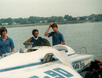
Delta Lady |
It was named Gun Shy, by
two different owners, twice during its career.
Click here to view a slideshow as she loses her sponson as Gun Shy.
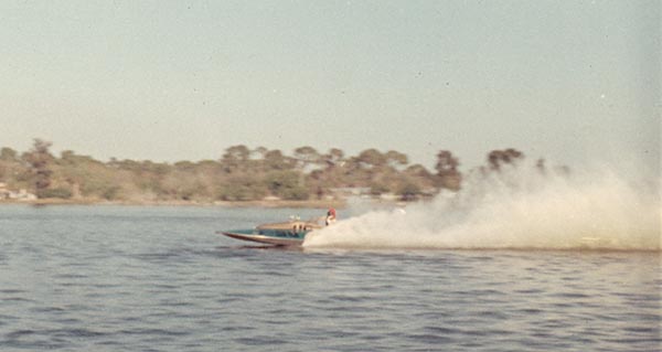
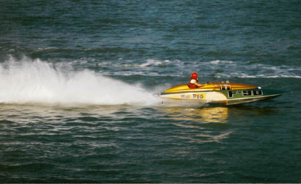
Miss Peg
Saint Petersburg, Florida
1968
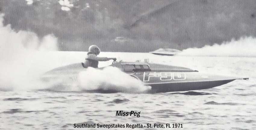
Miss Peg
Southland
Sweepstakes Regatta
Saint Petersburg, Florida
1971
Above 2 photos - courtesy
of Dennis Bowsher @ Roostertail
website.
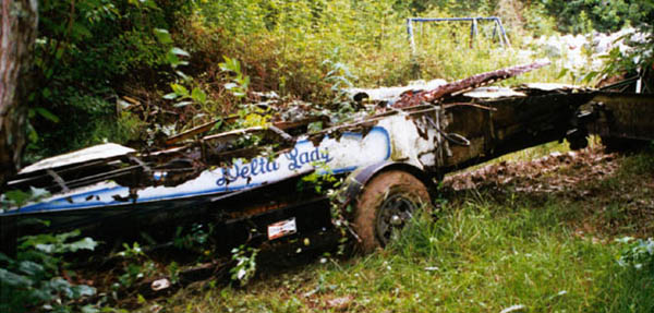
Jack Hines traveled to the
deep south to acquire this hydroplane.
He had to cut a path through
the swamp to get the hydroplane out.
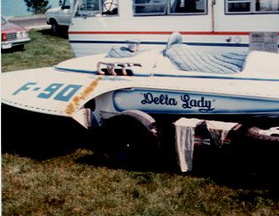
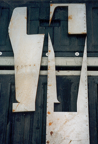
The majority of the hardware
came with the hydroplane.
Note the sponsons rotted and
fell off the hull.

THE REBUILD
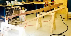
The start of every vintage
hydroplane starts with making the two motor stringers.
After cutting and final shaping
they are ready and become the backbone for every hydroplane.
Jack was fortunate to get
blueprints from the former owner.
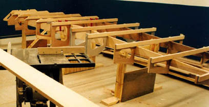
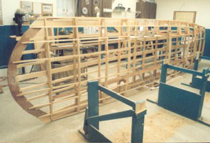
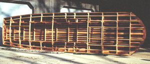
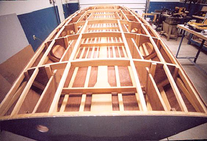
The frames are bolted to the
motor stringers and the skeleton of the hull is becoming apparent.
All hydroplanes are started
out by building them upside down.
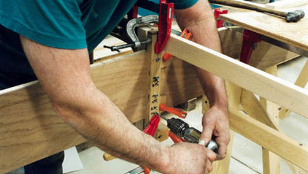
The board Jack is drilling
through looks like a setup piece of lumber for installation of the bolts
that attach the frame to the stringers.
Careful measurements are marked
on the motor stringers for proper placement of the frames.
Looks like a couple of more
frames to finish before installation can begin for the keel and battens.
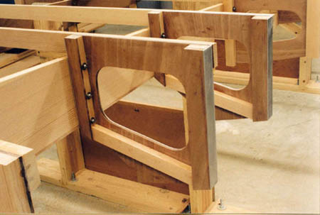
Quality work is displayed
is this closeup photo.
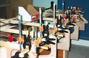
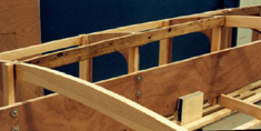
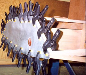
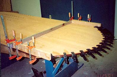
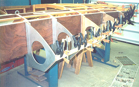
Clamping the chines.
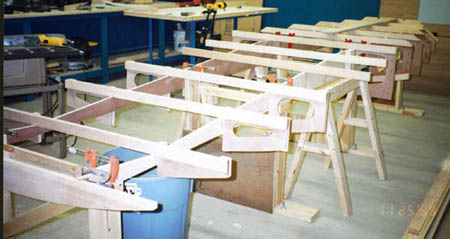
The chine framing is in place.
A trial fit of the shear batten
to locate the mortises that will be cut into each of the twelve frames.
These mortises have two angles
to them, reflecting both the vertical and horizontal curvature of the hull.
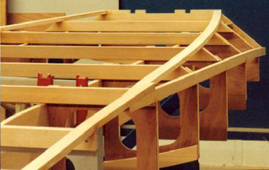
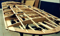
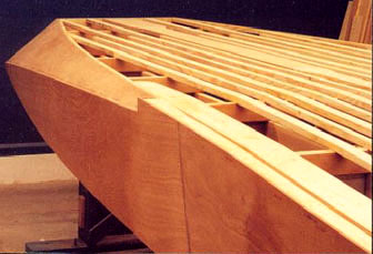
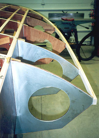
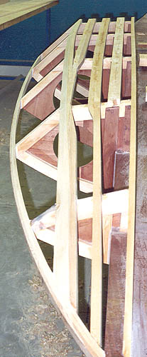
This view shows the keel
and bottom battens fitted to the transom.
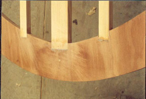
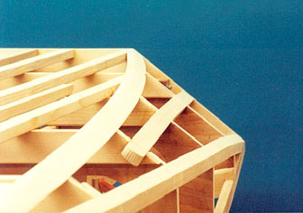
The curved nose piece, laminated
from three sections of marine plywood with keel and battens mortised in
place.
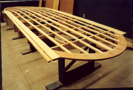
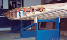
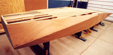
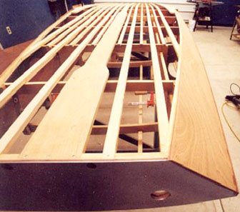
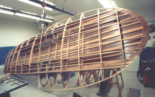
Bottom framing is now complete
and the hull is ready for its first turn over.
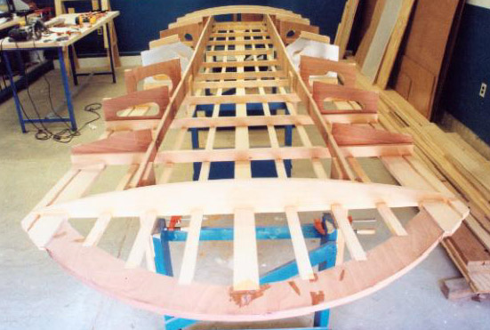
After some modification to
the jig, the boat is turned upright and placed back on the jig.
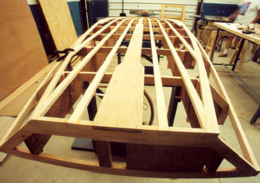
Deck beams and shears are
to be fitted next.
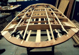
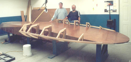
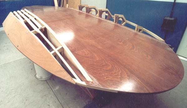
A front shot of Miss Peg.
It looks like Jack is almost ready to start fitting some of the plywood
skins to this famed F-Class hydroplane.
This Ron Jones design is simply
in a class by itself. Very clean lines and smooth features is going to
make this hydroplane quite special.
I'm sure Mr. Jones would be
very complimentary of the fine workmanship being put into this (new) vintage
hydroplane.
Below are more photos and
text sent in by Jack.
Installing the front deck
battens.
Where the battens intersect
the nose there is a compound angle that becomes more severe as you move
away from the center of the boat.
You also have to be sure the
taper at the nose is even so the finished nose will be of an even thickness
all the way across.
I started with the short pieces
to get the feel of fitting everything up.
The two outside battens run
almost the full length of the boat and are quite flimsy...a challenge in
patience!
I wanted to include some wood
from the original boat and have it be visible.
Found some stringer parts
that weren't too horrible.
Denailed, planed them down,
and bonded a piece of 3mm plywood to the back.
These formed the longitudinal
frames of the driver's and engine compartment.
I started to install the deck
beams perpendicular to the bottom of the boat, this would have required
fairing each batten off along its entire length.
Both a lot of unnecessary
work and weakening the batten.
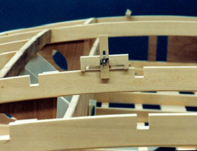
This tool allows marking of
the mortise at 90 degrees to the tangent of the decks curvature, and to
the correct depth.
The adjustable part is about
1/32" narrower than the batten to allow fitting.
A few strokes with a file
and you are good to go.
Depending on which end of
the boat that you are working on, the mortise bottoms are tapered to reflect
the deck curvature.
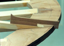
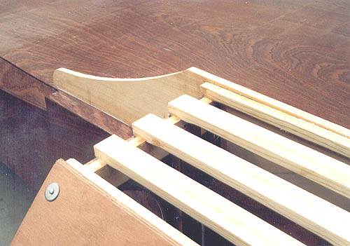
I was having trouble visualizing
where the deck battens would run out through the nosepiece, so I made this
notched piece of plywood.
You bend the batten down until
it fits against the nose, then you can measure up from the underside to
calculate the finished thickness of the nose.
To adjust, slide the batten
fore and aft until you get the thickness desired.
I have finished fairing the
left non-trip and most of the right.
The next step is to get batten
bonded, and finish up on the fairing and get some plywood cut.
There is a half batten on
the right side that extends from the transom, forward 3 frames.
This wasn't on the plan, but
is on the boat.
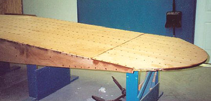
Last weekend I managed to
complete the right side plywood and rough cut the first bottom piece.
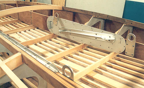
As you can see the aluminum
has been fitted to the transom.
I wanted to put this on first
so the side plywood would cover the edge...it makes for a more finished
look.
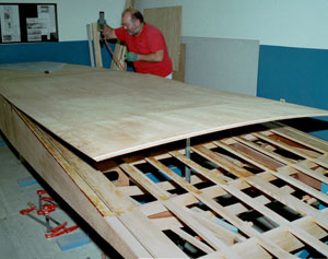
I decided to install the bottom
of the hull in three sections. We had 10' sheets of plywood but either
way the joint came in at the hull break. The length of this hydroplane
is 19'. I flow coated the back of all the plywood first with a sanding
sealer to smooth out the rough spots. I installed the rear sheet, about
6' long, first. Using a slow hardener, I barely had enough time to
get all surfaces coated before the resin started getting too sticky to
bond well.
The next sheet was a full sized
one and posed the intimidating problem of how to get all the surfaces coated
in time. Wasted quite a bit of time thinking about a solution.
Finally.......went with an extra slow hardener, turned the heat off in
the shop and got a gang together. It went well, the only problem was not
being able to clean up the squeeze out.
The nose shown here after notching
out for the sponson shear, went on without a hitch.
Sanding, sanding, and more
sanding. Plugged all the staple holes with resin mixed with plywood sawdust.
I blocked sanded down some
variations at the seams. On one particular high spot, I used the belt (gouge)
sander......never again!!! Continued on using only elbow grease. After
the sanding work was completed, I applied two coats of resin to all surfaces
after sucking up all the dust and wiping down with a tack cloth.
 Gathered up the gang again and lifted the hull off its fixture and carried
it outside. We built temporary supports on the jig to support the afterplane,
carried the boat back in and set her down. Other supports were fitted to
hold up the nose. We made everything for temporary use because the hull
will have to be turned again to build the sponsons. Gathered up the gang again and lifted the hull off its fixture and carried
it outside. We built temporary supports on the jig to support the afterplane,
carried the boat back in and set her down. Other supports were fitted to
hold up the nose. We made everything for temporary use because the hull
will have to be turned again to build the sponsons.
This has been the hold up,
no sponson design that reflects those on the boat in 1968. We are
working to resolve this, hopefully after the first of the year. So...currently
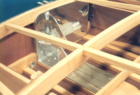
the plan is to clean up the inside, install engine compartment hardware,
lifting rings, and transom/strut/rudder supports.
|
 |
After turning the boat over
last December 2001, the first order of business was to sand away the squeeze
out left from bonding the bottom plywood. This turned out to be a larger
job than I had planned, considering there are 16 battens across the bottom!!
Even after using an extra slow hardener, couldn’t get it all removed before
curing. Splitting time up between sanding; the engine compartment metal
was cleaned up, new lifting eyes machined and all bonded into the hull. |
The original boat had a steel
rudder and strut reinforcement that was too badly rusted to reuse. I made
up a new one from some aluminum plate. The welding didn’t go too good and
the whole thing was badly distorted, I’ll have to cut it apart and find
a better welder.
Steering box was rebuilt and
the other metal parts were made ready to install. |
 |
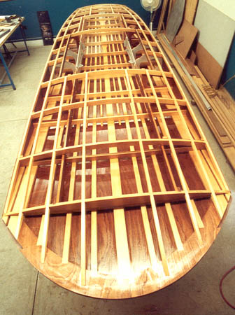 |
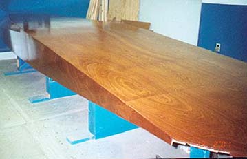
The entire hull was cleaned
and wiped down; two coats of CPES were applied to seal everything up. This
sealer really soaks into the wood, especially on the end grain. It works
the same as an epoxy primer and is compatible with varnish or other epoxy
surface finishes. CPES is a solvent based product so make sure a respirator
is used. |
| The sponsons have been a major
question mark since this project was started. They had completely rotted
off the boat, and had been modified from the original design about 1967.
After exhausting sources from former crew members, Ray Dong agreed to meet
with Ron Jones Sr. Several people had stated that the ’67 sponsons
were very similar to those on the early Jones cabovers. Ron’s thoughts
and recollections were noted. This information and data from plans were
fed into a computer by Randy Linn (Linn Racing) and we had a design. Major
changes were in dihedral and angle of attack. The longitudinal step in
the running surface was also eliminated. Hindsight wise, building frames
directly from this information isn’t the best way to go. Building frames
from some inexpensive material and mocking them up on the boat would have
saved time, money and aggravation. There were problems getting a fair line
on the shear, several frames had to be adjusted to correct the line. I
now have a large expensive pile of useless frames!! |
 |
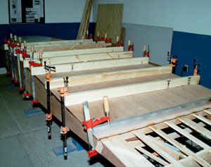
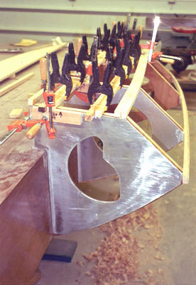
| The last two frames were bonded
to an aluminum pan to carry the loads back into the hull. Laminated the
shear batten in three pieces, one 3/4 piece of lumber wouldn’t make the
curve at the nose without breaking. I was glad that the boat was right
side, up made the job of fastening the frames easier and also visualizing
the shear batten line. |
 |
December 5 was turn over day.
This went pretty good considering an eight foot wide boat in a nine foot
high garage!! It took four of us with the help of an overhead hoist. She
went back on the original jig.
 |
 |
Frames were faired as the
rear 32 inches is perfectly flat and to allow full contact with battens
as they curve to the bow. Sponson battens are being installed in this view.
Again the battens were split lengthwise into two ¾ square pieces
to allow for the twist as they head to the front. No permanent fasteners
were used. Screws that run thru the aluminum runner and plywood into the
framing will be installed later. It’s difficult to visualize how the running
surface and side of the sponson run out into the nose of the boat. I positioned
the bottom shear where it looked right. Later, had to cut it loose and
reposition at the bow. Only one side of boat was built at a time to avoid
multiple mistakes. |
 |
Started
fairing the side of sponson from rear carrying it forward, the running
surface was done by the same method. I think it gives a sight line and
a flat surface to work from. A long straightedge helps a lot.
| The air trap lumber was fitted
and bonded in, followed by its 6mm plywood facing. Scribing and fitting
these pieces to the bottom profile of the boat took quite some time. The
side plywood was roughed in and bonded, screws were removed just before
the epoxy cured…don’t get caught sleeping!! A final fairing of the
running surface and the deck shear and we’re ready for the running surface.
Planning on framing other sponson before covering this one, will be able
to transfer dimensions etc. |
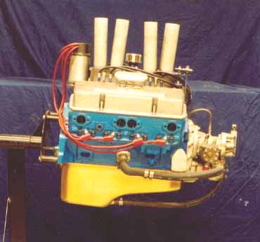
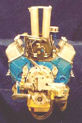
 |
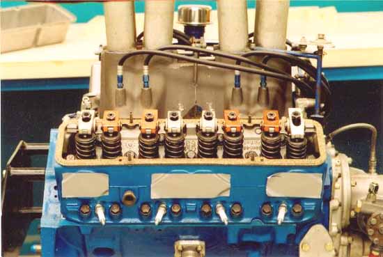
Motor is also being prepared.......more
to follow.
 |
 |
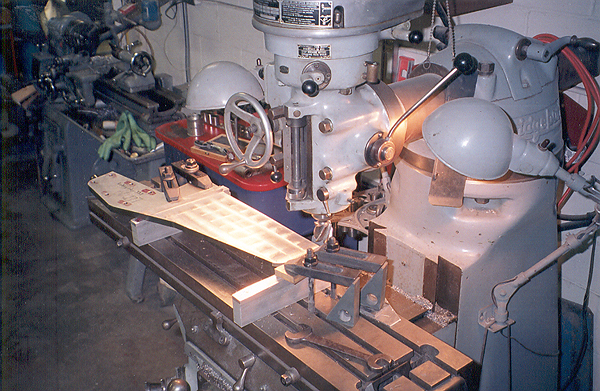
|
The rudder being machined.
Most of the great photos of
this project have shot, by none other than the Master himself,
Phil Kunz, who has been photographically
documenting the entire rebuild of the Miss Peg.
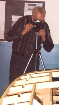
Thanks for all the wonderful
pictures!
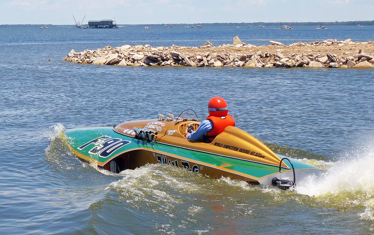
After a painstaking rebuild of the entire boat in Dayton, Ohio, Jack traveled
to Lake Palourde in Morgan City, Louisiana in July 2013, where the Miss Peg ran many races during
its career under all its different names - Gun Shy, Tin Horn, Miss Peg,
Delta Lady. A fitting tribute to have the boat's first run at its most raced venue.
Those involved with the boat by incarnation were present -
Gun Shy: Ennie Argence, Richard
Landaiche (nephew to Ennie), Roy Wilson Jr. (Sr.) drove after Ennie
hurt.
Tin Horn: Jerry Bile son of Harry (owner),
Clayton Boudreaux driver.
Miss Peg: Pat Buntin Miley (Bill's wife), Sean
Buntin (son), Damon King (daughter), Joey Nolan (Joe Nolan Sr. father crew),
Denver Ray Mut ( Melvin Mut father crew), Kip Fabre' (son of engine builder
Cliff), Jean Talliac (driver after Bill), Larry Farris (son of owner
Lawrence).
Gun Shy II: Robert and Mike Herrington
(owners/driver).
Delta Lady: Joyce Edmonston (wife of owner
Joe?).
Click here to view a 30 second (18 MB) video clip OR click here to view the same clip in HD (55MB) from a pass at New Martinsville, WV in 2013.
You will need Windows Media Player.
If you have any information,
home movies or photographs on his hydroplane, please email Jack (Dayton, Ohio)
© Jack
Hines
Back to the boats |
|
|